VoIP How to: Voice reinjection: Difference between revisions
m (Make clearer) |
|||
| (One intermediate revision by one other user not shown) | |||
| Line 37: | Line 37: | ||
* Gently unclip the 4 plastic clips which retain the circuit board in the outer shell, and lift out the circuit board. |
* Gently unclip the 4 plastic clips which retain the circuit board in the outer shell, and lift out the circuit board. |
||
You should now have gone from |
You should now have gone from<br /> |
||
[[ File: VDSL_SSFP_back.jpg]] |
[[ File: VDSL_SSFP_back.jpg]]<br /> |
||
to |
to<br /> |
||
[[ File: VDSL_SSFP_dismantled.jpg]] |
[[ File: VDSL_SSFP_dismantled.jpg]] |
||
| Line 54: | Line 54: | ||
This is an untidy solution, and relies on having the right parts to hand. |
This is an untidy solution, and relies on having the right parts to hand. |
||
One needs an ADSL microfilter |
One needs an ADSL microfilter as supplied with modem/routers over the years. It needs to be of the type where the connection to the line is made with a short BT plug to an RJ11 plug (American style) - i.e. the microfilter has two RJ11 sockets on it, and one BT phone socket. One also needs an ''appropriate'' RJ11 plug to RJ11 plug lead. Remove the existing RJ11 lead from the VDSL SSFP, plug one end of the new RJ11 lead into the VDSL SSFP, and the other end into the 'line' connection of the microfilter. Now plug the free end of the old RJ11 lead into the microfilter, and ensure the modem/router regains sync. Now the phone socket on the microfilter is connected to the copper pair. |
||
There |
There is a gotcha regarding the wiring of RJ11 sockets. The VDSL SSFP uses pair 1 (pins 3 and 4) on the connection for the modem/router. I have two suitable microfilters, but they both have the RJ11 (or RJ14 ?) line socket wired using pair 2 (pins 2 and 5) instead (although the RJ11 out to the modem/router is wired as pair 1), so one needs a crossover RJ11/14 cable between the VDSL SSFP and the microfilter. It's easier if one has a box of spare microfilters and leads... the crossover cable would need to wire pin 2 at one end to pin 3 at the other end, 3 to 2, 4 to 5, and 5 to 4. |
||
== Earlier NTE5 with MK3 VDSL Interstitial faceplate == |
== Earlier NTE5 with MK3 VDSL Interstitial faceplate == |
||
Latest revision as of 23:12, 14 February 2022
In BT terminology, Voice Reinjection is the way to route voice signals from a VoIP service onto the existing home telephone wiring. This will become more common as copper pairs are replaced by optical fibre.
In the meantime, if you have a copper pair from A&A (i.e. without telephone service on that copper pair) and use VoIP, you may want to route the voice signals from VoIP onto the existing home telephone wiring.
This page gives some ideas of how this can be achieved without installing extra phone sockets.
NTE5c and VDSL Service Specific FacePlate
A modern Openreach installation will terminate the copper pair on an NTE5c master socket which will have a VDSL SSFP clipped to the front of it.
The VDSL SSFP provides two sockets - an RJ45 to connect to the modem/router, and a telephone socket for a local handset. The VDSL SSFP also feeds the voice signals to the home telephone wiring via the NTE5c.
If one plugs an Analogue Telephone Adaptor into the router via Ethernet, then the ATA provides the voice signals on an RJ11 socket. This is fine to connect, using an RJ11 plug to phone plug lead (with ringing capacitor), to a local handset - but fails to connect to the home telephone wiring.
One can connect the ATA voice signals to the home telephone wiring, but it means some modifications to the VDSL SSFP. It's probably a good idea to buy a spare VDSL SSFP, so one can revert to a standard setup easily.
Modifying the VDSL SSFP
The following applies to the faceplate labelled Openreach MK4. These instructions may not be suitable for later versions if introduced in the future.
Warning If you install a faceplate with these modifications, you will no longer have access to the voice channel on the copper pair for testing purposes. You would have to remove the modified faceplate and either use the test socket on the NTE5c or install a unmodified faceplate. Update there is an untidy way of gaining access, see below.
These modifications need some degree of technical know-how, and you might need to consult someone if you feel you don't have that know-how.
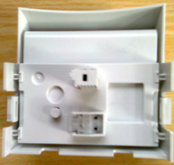
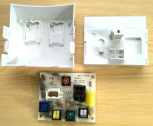
- Gently unclip the 4 plastic clips which retain the inner white plastic part of the VDSL SSFP from the outer shell, and lift the inner part out. Try to pull straight, as the metal pins of the telephone plug are attached to the circuit board and could be damaged if handled roughly
- Gently unclip the 4 plastic clips which retain the circuit board in the outer shell, and lift out the circuit board.
You should now have gone from

to

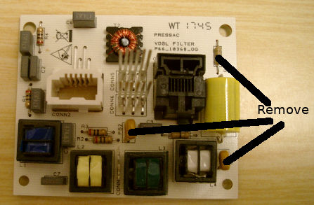
- Two components need to be removed, and it's recommended to remove a third one. The components to remove are labelled PS1 and PS2 on the circuit board - they may be orange in colour, and can be removed by desoldering or mechanical destruction.
- It's optional to remove a third component - the resistor labelled R6. The VDSL SSFP doesn't use the bell capacitor in the NTE5c - it provides its own bell capacitor (labelled C8). R6 connects the bell capacitor to the telephone socket, but we're now using the telephone socket as an input from the ATA and so R6 isn't needed and might cause confusion if ringing ever came down the lead from the ATA. On the other hand, with R6 still in place one could use a 2 to 1 adaptor in the phone socket and plug in a local handset. One could always compromise and just disconnect one leg of R6...
Reassemble the VDSL SSFP and install it on the NTE5c. One can now simply connect the ATA phone socket to the phone socket on the VDSL SSFP with an RJ11 plug to BT phone plug lead. It doesn't need to provide a bell capacitor. A lead from an old modem (pre broadband) may be ideal.
Gaining access to the voice channel on the copper pair
This is an untidy solution, and relies on having the right parts to hand.
One needs an ADSL microfilter as supplied with modem/routers over the years. It needs to be of the type where the connection to the line is made with a short BT plug to an RJ11 plug (American style) - i.e. the microfilter has two RJ11 sockets on it, and one BT phone socket. One also needs an appropriate RJ11 plug to RJ11 plug lead. Remove the existing RJ11 lead from the VDSL SSFP, plug one end of the new RJ11 lead into the VDSL SSFP, and the other end into the 'line' connection of the microfilter. Now plug the free end of the old RJ11 lead into the microfilter, and ensure the modem/router regains sync. Now the phone socket on the microfilter is connected to the copper pair.
There is a gotcha regarding the wiring of RJ11 sockets. The VDSL SSFP uses pair 1 (pins 3 and 4) on the connection for the modem/router. I have two suitable microfilters, but they both have the RJ11 (or RJ14 ?) line socket wired using pair 2 (pins 2 and 5) instead (although the RJ11 out to the modem/router is wired as pair 1), so one needs a crossover RJ11/14 cable between the VDSL SSFP and the microfilter. It's easier if one has a box of spare microfilters and leads... the crossover cable would need to wire pin 2 at one end to pin 3 at the other end, 3 to 2, 4 to 5, and 5 to 4.
Earlier NTE5 with MK3 VDSL Interstitial faceplate
An earlier Openreach installation will terminate the copper pair on an NTE5 master socket, to which a MK3 VDSL interstitial faceplate has been added, moving the lower section of the master socket to the front of the faceplate.
To achieve Voice Reinjection, unscrew the lower section of the faceplate and gently pull it free. The home telephone wiring is attached to this lower section. One requires an RJ11 plug to BT phone socket lead with bell capacitor. Plug the BT socket of this lead into the skeleton plug on the back of the lower section just pulled free. Replace the screws on the main body of the master socket.
The installation could be tidied up if one has a spare lower section for an NTE5 to replace the one pulled free.
